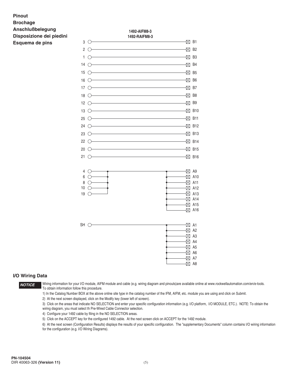
6) at the next screen (configuration results) displays the results of your specific configuration. Add to basket pricing/availability request.
Rockwell Automation 1492AIFM83_RAIFM83 Analog Interface Modules User Manual Page 5 / 6
Fusing — fuse holders are included with the aifm.
1492 aifm8s 3 wiring diagram. At the next screen click on accept for the 1492 module. The cables are prewired and pre tested which make them a preferred choice over conventional wiring systems in the industry. Simplifies design and engineering time.
Fusing — fuse holders are included with the aifm. 4.33 in l x 2.74 in w x 3.27 in h. Explore product and service content by industry.
Wiring — refer to the label section on page 174. Fuses (5 x 20 mm) are not included. 1492 aifm8s 3 wiring diagram.
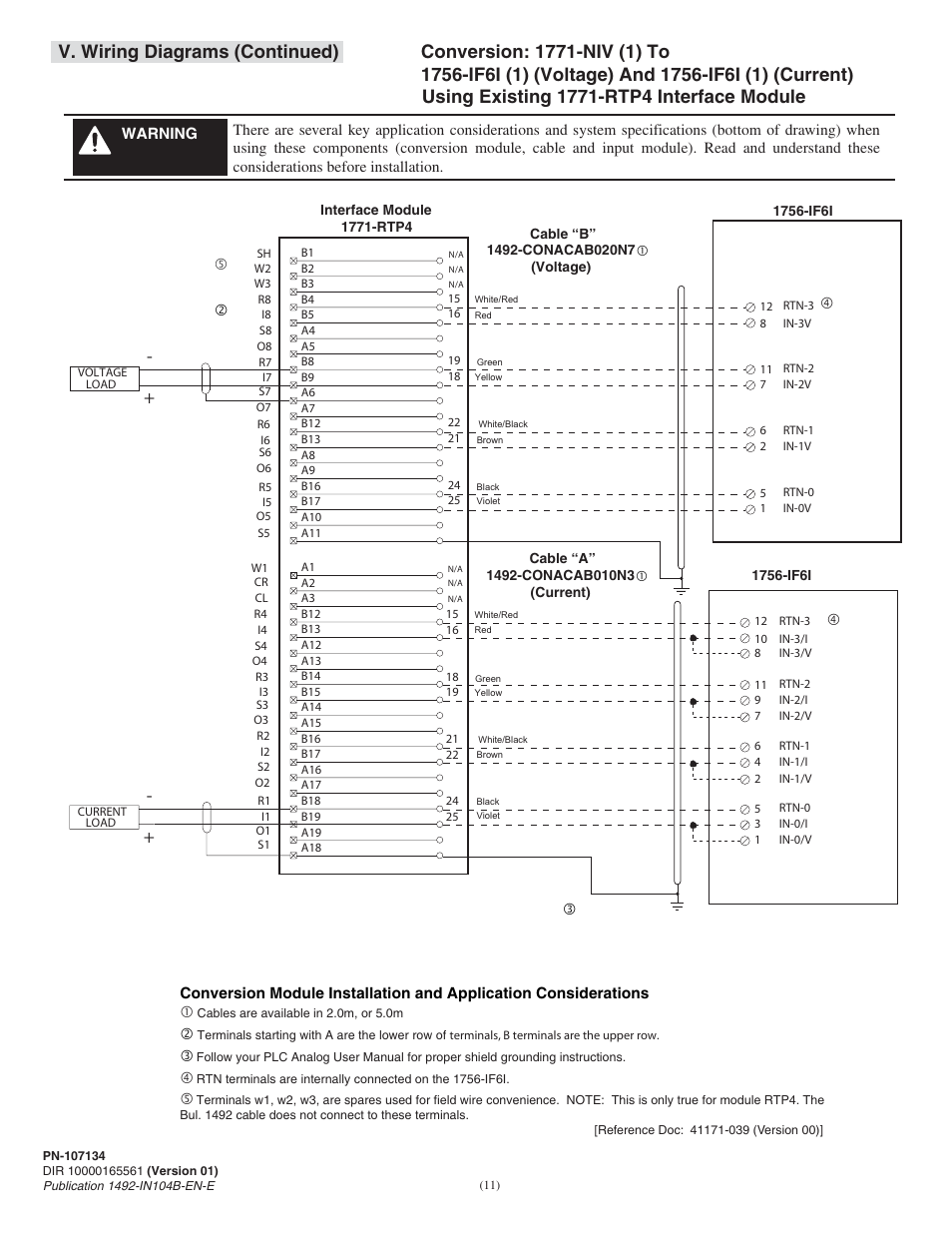
Wiring — refer to the label section on page 174. The rockwell automation bulletin 1492 hosts a wide series of analog programmable controller wiring systems. A wiring diagram is a kind of schematic which uses abstract pictorial symbols to show each of the interconnections of components inside a system.
1492 aifm8 3 wiring diagram. Literature library | rockwell automation Fuses (5 x 20 mm) are not included.
7 rows increases machine building productivity. 1492 8 inputs 8 outputs 0 to 132 vacvdc 2 a screw terminal 0 to 60 deg c metal 433 in l x 274 in w x 3. 4) configure your 1492 cable by filing in the no selection areas.
Do not exceed 2 a per input, 12 a per aifm. 5) click on the accept key for the configured 1492 cable. Do not exceed 2 a per input, 12 a per aifm.
1492 aifm8s 3 wiring diagram: Isolation — the fuse clips and blown fuse Wiring — refer to the label section on page 174.
Rockwell automation(1492 product lines) packaged solutions (146. Compatibility — to ensure proper operation with the i/o module, do not exceed the voltage and current ratings of the aifm. The interface modules are mounted onto a standard din #3 rail.
Isolation — the fuse clips and blown fuse